
A few months after I finished the car, I could dismantle it and reuse some pieces. But I hadn't documented it - so I thought I would document the dismantling process to show how the final car had been completed.
I've uploaded a .mpg file of the car being used; it's 32 Mb in size, sorry about that.
The car has front and rear bumpers; made out of 3-ply and bent to shape using a kitchen saucepan steamer, then painted and with holes drilled for the coloured LEDs for brake lights, reverse lights and indicator lights. (Wood bends easily when steamed, and stays in the bent shape once cooled).
There are two arduinos within the car; one for reading the transmitter, and one for controlling the motors and lights. The separation of these functions is necessary in all robots; the arduino does not have adequate multi threaded architecture to undertake these separate functions on one CPU or in one software process (ie. in one program).
The power supply is a 3300 mAh rechargeable bought from ebay.co.uk. It's mounted in the middle of the car, between the chassis top and bottom, next to the motors. It was 2mm too wide, which caused an entertaining day of anglo-saxon discussions, and the eventual solution was to snip off 2mm off the (unused) inside plastic axles with a hacksaw.
|
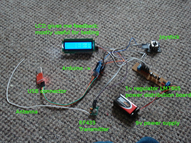
The transmitter. I never got round to making a neat box to mount it in. All the components are detailed below, with the Arduino pin connections and the code I wrote for it. |
|
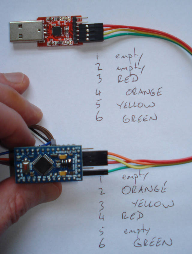
| Transmitter USB TTL to Arduino. |
|
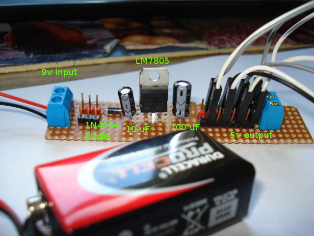
| Transmitter 5v regulated power supply. A 9V power supply goes through a single diode 1N4004 and a LM7805 regulator, surrounded by a 10uF and a 100uF capacitor. Strips of connectors and a header provide several connections for output. Neat job. |
|
| Transmitter, RF433 - apart from the obvious +5V and GND, connect the output to Arduino pin 12. |

|
| LCD for feedback. The LCD here is upside down, with the LCD controller PCF8574T soldered on, and electrically isolated using a piece of cardboard between them. Apart from the obvious +5v and GND, connect SCL to Arduino A5 and SDA to Arduino A4. |

|
|
Joystick. Apart from the obvious +5V and GND, connect vrX to Arduino pin A3 and vrY to Arduino pin A2 and SW to Arduino pin 2. |

|
This code is fairly basic, and can easily be expanded to do more complex things in a cleverer way.
What is sent from the transmitter is a 2-character code in a clear-text readable format.
The first character is used to determine whether the joystick is static/forwards/backwards, and
the second character is used to determine whether the joystick is static/left/right.
The switch (on the joystick) is not used.
		/*
Read the joystick. SWITCH HAS PULL UP RESISTOR !!!!!!!!.
Use wireless transmission ...
*/
#include <RH_ASK.h>
#include <SPI.h> // Not actually used but needed to compile
#include <Wire.h>
#include <LiquidCrystal_I2C.h>

LiquidCrystal_I2C lcd(0x27,16,2);  // set the LCD address to 0x27 for a 16 chars and 2 line display

RH_ASK wirelessDriver;

int analogInputPinX   = A3; // Arduino pin for the joystick X and Y inputs
int analogInputPinY   = A2;
int digitalInputPin  = 2;   // Arduino pin for the joystick switch
int wait = 1000;
int inputX;                 // analogRead for the joystick X and Y
int inputY;
int inputSW;                // digitalRead for the switch; nb pull UP resistor.


const int STATIC = 1;      // Direction constants transmitted from the car
const int FORWARDS = 2;
const int BACKWARDS = 3;
const int LEFT = 4;
const int RIGHT = 5;
int x_dir;               // Holds one of the direction constants above
int y_dir;               // Holds one of the direction constants above

void setup()
{
  lcd.init();                      // initialize the lcd

  // Print a message to the LCD.
  lcd.backlight();
  lcd.print("Joystick Transmit");
  lcd.setCursor(0,1);
  lcd.print("Starting ...");

  pinMode(analogInputPinX,   INPUT);
  pinMode(analogInputPinY,   INPUT);
  pinMode(digitalInputPin,   INPUT);
  digitalWrite (digitalInputPin, HIGH); // Joystick has a pull up resistor.

  if (!wirelessDriver.init())
      {
         Serial.println("Wireless init failed");
         delay(10000);
      }

  Serial.begin(9600);
  delay(2000);
}

void loop()
{
  //delay(wait);
  inputX = analogRead(analogInputPinX);
  inputY = analogRead(analogInputPinY);
  // Serial.print("X is read as ");
  // Serial.print(inputX);
  // Serial.print(" and Y is read as ");
  // Serial.println(inputY);
  // Serial.println("");

  inputSW = digitalRead(digitalInputPin);
  if (inputSW == LOW)
      {
      Serial.print("YAY ! Digital switch is Pressed ! ");
      }

  x_dir = STATIC; // Normal X position is 522
  if (inputX < 510)
    {
      x_dir = LEFT;
    }
    if (inputX > 530)
    {
      x_dir = RIGHT;
    }
  y_dir = STATIC; // Normal Y position is 513
  if (inputY < 500)
    {
      y_dir = FORWARDS;
    }
    if (inputY > 530)
    {
      y_dir = BACKWARDS;
    }

   lcd.clear();
   lcd.setCursor(0,0);
   lcd.print("X dir is ");
   lcd.print(x_dir);
   lcd.setCursor(0,1);
   lcd.print("Y dir is ");
   lcd.print(y_dir);
  sendMessage(x_dir, y_dir);
}

void sendMessage(int sendX, int sendY)
{
char msg[3];

  msg[0] = sendX;
  msg[1] = sendY;
  msg[2] = '\0';

  wirelessDriver.send((uint8_t *)msg, strlen(msg));
  wirelessDriver.waitPacketSent();
 Serial.print("SENT MESSAGE : ");
 Serial.print(sendX, HEX);
 Serial.println(sendY, HEX);
 // Serial.println(msg);
  delay(200);
}
|
The car is an engineering marvel, and I take my place alongside
Isambard.
If anyone gets as far as this and actually reads
this, then I guess the reality is: well, it's not bad for a first attempt at a RC car, created from scratch.
Leave me some 'Well Done' feedback !
The car uses 2 arduinos; one to hang around and wait for a radio signal from the transmitter, and the other to
control the motors and the lights. Looking at the robots provided on the arduino website, I see they use 2
arduinos as well. The reason is straightforward - an arduino cannot do 2 things at the same time. If the code
is waiting for a radio signal to arrive, then it can't be controlling the motors as well. An arduino is _not_
powerful enough to run multi-threaded systems, or a workable interrupt cycle ! So - simply use 2 arduinos.
The final wiring required 3 attempts, and I learned the importance of a well designed power distribution board to
minimise wiring tangles.
| This is the car ... |

|
| And these are the components. |

|
Since it's impossible to see the individual workings, let's start taking it apart.
The 4 motors are connected through a slot in the top chassis, so can be removed straightaway, separating the
electronics from the chassis.
The lights are the first things for me to remove and get out of the way.
The lights were something I wanted to do as a challenge to myself. The reverse lights come on and stay on while
reversing. The brake lights come on and stay on when not moving. The indicators flash twice then stop when turning left or right.
That's all controlled in the code, of course. The wiring was fiddly around the chassis, but is was the
obvious loop of wire from an arduino pin, thru a resistor and a couple of coloured LEDS, and back to a common ground. Set the
arduino pin high; and the lights come on.
|
The shift register for the lights, crudely mounted. There's some dodgy cabling underneath, for 5V and GND to the
correct pins. There are 4 outputs used, for the left indicator lights, right indicator lights, brake lights and reverse lights. I'm not documenting the wiring on the chassis for the lights, since you can guess that yourself. If you want the light on - set the pin high ! The 3 shift register control pins are connected to the arduino pins 2, 3 and 4. Yellow - pin 2. Green - pin 3. Blue - pin 4. |

|
And with the lights disconnected and the motors disconnected, we can more clearly see the underlying construction.
|
With the bumpers unscrewed, we can see the wiring for the lights. It's a simple wire circuit from the
arduino pinout, to a series of coloured LEDs, and back to a common ground on the arduino. |

|
| The arduino that is dedicated to the RF433 transmissions. The RF433 receiver is connected to Arduino pin 11; the two arduino's are connected via pins A0 thru A3. |

|
The receiver arduino is connected to the motors arduino using 4 cables, which are permanently held high or low
indicating the last direction command that was received from the transmitter.
Normal binary is being used; each cable is set either high or low, (0 or 1), giving us
16 possible directions (2^4) to travel in. Only 9 directions are being used in the current setup.
The code uses the RF433 library to hang around waiting for a radio signal to arrive. Given a signal, which was
transmitted as a 2-byte character array, it decodes it into left/right/back/fwd,
and sets the 4 cable communicator to the appropriate high or low.
The motors arduino can then read these cables at any time, without waiting, to determine whether the direction has
changed.
#include <RH_ASK.h>
#include <SPI.h> // Not actually used but needed to compile

RH_ASK wirelessDriver;

int RXpowerPin = 3;
int i;
char rcvString[200];

int bit0 = A0;
int bit1 = A1;
int bit2 = A2;
int bit3 = A3;

const int STATIC = 1;      // Direction constants transmitted from the car
const int FORWARDS = 2;
const int BACKWARDS = 3;
const int LEFT = 4;
const int RIGHT = 5;

int x_dir;
int y_dir;

void setup()
{
  pinMode(bit0, OUTPUT);
  pinMode(bit1, OUTPUT);
  pinMode(bit2, OUTPUT);
  pinMode(bit3, OUTPUT);

  digitalWrite(bit0, LOW);
  digitalWrite(bit1, LOW);
  digitalWrite(bit2, LOW);
  digitalWrite(bit3, LOW);

  pinMode(RXpowerPin, OUTPUT);
  digitalWrite(RXpowerPin, HIGH);

  Serial.begin(9600); // for serial monitor output
  if (!wirelessDriver.init())
     {
      Serial.println("init failed");
      delay(10000);
     }
}

void loop()
{

  uint8_t buf[RH_ASK_MAX_MESSAGE_LEN];
  uint8_t buflen = sizeof(buf);

    if (wirelessDriver.recv(buf, &buflen)) // Non-blocking
    {

        // Message with a good checksum received, dump it.
        // wirelessDriver.printBuffer("Got:", buf, buflen);

      x_dir = buf[0];
      y_dir = buf[1];
  // Serial.print("RECEIVED MESSAGE : ");
  // Serial.print(buflen);
  // Serial.print(x_dir, BIN);
  // Serial.println(y_dir, BIN);

      switch (x_dir)
      {
        case STATIC:

          if (y_dir == STATIC)
            {
              sendSignal(0, 1, 0, 1);
            }
          if (y_dir == FORWARDS)
            {
              sendSignal(0, 0, 1, 0);
            }
          if (y_dir == BACKWARDS)
            {
              sendSignal(1, 0, 0, 0);
            }

          break;

        case LEFT:

          if (y_dir == STATIC)
            {
              sendSignal(0, 1, 0, 0);
            }
          if (y_dir == FORWARDS)
            {
              sendSignal(0, 0, 0, 1);
            }
          if (y_dir == BACKWARDS)
            {
              sendSignal(0, 1, 1, 1);
            }
          break;

        case RIGHT:

          if (y_dir == STATIC)
            {
              sendSignal(0, 1, 1, 0);
            }
          if (y_dir == FORWARDS)
            {
              sendSignal(0, 0, 1, 1);
            }
          if (y_dir == BACKWARDS)
            {
              sendSignal(1, 0, 0, 1);
            }
          break;

        default:
          Serial.println("Received X as UNKNOWN");
          break;
      }

    }
 //   Serial.println("Waiting for 1 second ...");
// delay(1000);
}
// PAUL ! DO IT THIS WAY ROUND
void sendSignal(int sendBit3, int sendBit2, int sendBit1, int sendBit0)
{
  Serial.print("Sending ");
  Serial.print(sendBit0);
  Serial.print(sendBit1);
  Serial.print(sendBit2);
  Serial.print(sendBit3);

  if (sendBit0 == 0)
      {
      digitalWrite(bit0, LOW);
      }
  else
      {
      digitalWrite(bit0, HIGH);
      }
  if (sendBit1 == 0)
      {
      digitalWrite(bit1, LOW);
      }
  else
      {
      digitalWrite(bit1, HIGH);
      }
  if (sendBit2 == 0)
      {
      digitalWrite(bit2, LOW);
      }
  else
      {
      digitalWrite(bit2, HIGH);
      }
  if (sendBit3 == 0)
      {
      digitalWrite(bit3, LOW);
      }
  else
      {
      digitalWrite(bit3, HIGH);
      }

}
|
This is possibly the most complicated part to document.
The heart of the motor control is two L293D motor control chips, and a SN74HC595N shift register.
Surrounding those are the parts of the power supply; we'll deal with those next.
Power distribution board. The connector from the battery gives us a 7.2V rail, from which the
motors draw their power.
A spur comes off this 7.2V rail, passes thru a 5v regulator, and returns back to give us a 5V rail, from
which the electronics draw their power.
The third rail on the power dist board is a common GND rail.
You can see just how many power connections are required by counting the number of black GND cables attached
to that GND rail.
|
The 5v regulator (L7805) is on the left. It draws power from the 7.2V rail, and creates a new 5V rail to run the
electronics. You can see just how many power connections are required by counting the number of black GND cables attached to that GND rail. |

|
Removing those power supply components should start to expose the wiring underneath for the two L293D motor control chips and the shift register.

|
Once we've got rid of the 3 shift register control cables, the final 4 cables to the arduino are the PWM speed controls, one for each motor.
| The 4 pins used for the 4 PWM motor inputs are arduino pins 5, 6, 7 and 11. The corresponding L293D pins are pins 1 and 9 on each of the 2 L293D chips. |

|
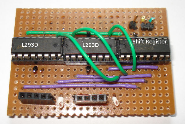
There are 3 chips; the shift register on the right, and 2x L293D motor control chips left and middle.
Using our handy shift register layout guide,
we can see that each output is connected to pins on the L293D.
| With power cables snipped off, PWM speed control cables gone, we can look at the final layout. |
|
What we need now are the pinouts for those chips:

|

|
From the diagrams, we can see that there are 8 outputs from the shift register, and we can see that each L293D requires 2 inputs
to determine the direction.
From the photo, we can see that outputs 0 and 1 go to the L293D direction control inputs for the first motor.
So we can see how the 8 outputs of the shift register control the direction of each of the 4 motors, and a quick glance
at the code below confirms this; functions setMotorForwards(), setMotorBackwards() and sendMotorArray().
The L293D has a maximum power output of 1A. I don't know the rating of the motors I got with the chassis.
The final speed of the car was acceptable for indoors, but was nothing powerful.
Looking at the photos now, I seem to have connected 2 of the motors to the 7.2v rail, and accidentally connected the
other two motors to the 5v rail ! I didn't notice that at the time.
I went through a number of power distributions boards, as the wiring got more complicated. The final version (shown)
is the design I will use in the future - a long piece of stripboard, with 3 rails and a 5v regulator.
I liked my design of 4 cables to connect the two arduinos. It worked extremely well, the obvious limit of 16 commands
that can be passed was not exceeded. Other methods would be a serial i2c link, but serial comms I wanted to avoid.
The libraries for the RF433 were excellent.
The wiring for the LEDs (lights) was "interesting". I was pleased to include it, and create the code to control them; however,
the woodwork to create the bumpers and then the wiring for the light circuits was a bit of a pain.
I never got round to including the sonic distance sensor. I couldn't really see a need for it. Plus, making it work
accurately during tight cornering would be impossible with only one forward-facing sensor.
Using the shift register to control the direction of 4 motors was a stroke of genius.
All in all, I am happy with the final result. I learned a lot and had great fun. It absorbed me for several months !
This is the code for the arduino that controls the motors (and also the lights).
The main loop continuously does 3 things:
- Check the 4-cable connector to see if the direction has changed
- Write a value to motors, indicating change of speed
- Check the lights to see what is flashing, and change if needed.
/*
 4WD Car chassis.
 Paul Goodliffe, May 2014
 Motor and lights
 */

int IRbit0 = A0;   // These 4 pins read the HIGH / LOW value from the sensor arduino,
int IRbit1 = A1;   // allowing us up to 16 possible values for the joystick direction.
int IRbit2 = A2;
int IRbit3 = A3;

long myTimer = 0;      // The timers are for debug purposes only
long irTimer = 0;
long movementTimer = 0;
long lightsTimer = 0;
long tmp1Timer = 0;
long tmp2Timer = 0;
long tmp3Timer = 0;
int loopCounter = 0;

int joystickDirection; // The main variable holding the direction to go (1 - 9)

 int whatAmIDoing;
 const int Myforward = 1;
 const int Mybackward = 2;
 const int Mystopping = 3;
 int leftSpeed = 0;            // Between 0 and 250 for m1_speed
 int rightSpeed = 0;

 long brakeTimer;
 boolean brakeTimerRunning;
int lightsDataPin = 2;        //Define which pins will be used for the Shift Register control
int lightsLatchPin = 3;
int lightsClockPin = 4;

int lightsArray[8];   // Declare an arrary of 8 integers. Each value will be either 0 or 1.
int indicateLeftArrayNum = 3;
int indicateRightArrayNum = 2;
int indicateBrakeArrayNum = 1;
int indicateReverseArrayNum = 0;
int leftBlinking = false;
int rightBlinking = false;
long tmpTimer;
long lastTimer = millis();

 int motorArray[8];
 int motorDataPin = 12;        //Define which pins will be used for the MOTOR Shift Register control
 int motorLatchPin = 13;       // The shift register controls the L293D motor direction controls.
 int motorClockPin = 7;

//Motor one
int m1_speed        = 5;  // Must be PWM for speed control, so must be a pin on the Arduino
int m1_forward       = 0;  // Shift register pin; motor 1 direction.
int m1_backward      = 1;

//Motor two
int m2_speed        = 6;  // Must be PWM for speed control
int m2_forward       = 3;
int m2_backward      = 2;
//Motor 3
int m3_speed        = 10;  // Must be PWM for speed control
int m3_forward       = 4;
int m3_backward      = 5;

//Motor 4
int m4_speed        = 11;      // Must be PWM for speed control
int m4_forward       = 7;
int m4_backward      = 6;


// The main direction, forwards or backwards (or static) only needs to be set when it changes !
const int mainDirFwd = 1;
const int mainDirStatic = 2;
const int mainDirBack = 3;
int mainDirection = 0;

void setup()
{
  pinMode(IRbit0, INPUT);    // The 4 pins to read the HIGH or LOW values from the sensor arduino
  pinMode(IRbit1, INPUT);
  pinMode(IRbit2, INPUT);
  pinMode(IRbit3, INPUT);

  pinMode(m1_speed, OUTPUT);  // The 4 PWM pins for speed control of each motor
  pinMode(m2_speed, OUTPUT);
  pinMode(m3_speed, OUTPUT);
  pinMode(m4_speed, OUTPUT);

  pinMode(motorDataPin, OUTPUT);       // Motor Array pins
  pinMode(motorLatchPin, OUTPUT);
  pinMode(motorClockPin, OUTPUT);

  pinMode(lightsDataPin, OUTPUT);      // Lights Array pins
  pinMode(lightsLatchPin, OUTPUT);
  pinMode(lightsClockPin, OUTPUT);

  resetMotorArray();          // Set the arrays to 0 initially.
  resetLightsArray();
  mainDirection = mainDirStatic;

  Serial.begin(9600);
}

void loop()
{
  myTimer=millis();

  getJoystick();
  tmp1Timer=millis();
  irTimer = irTimer + (tmp1Timer - myTimer);

  movement();
  tmp2Timer = millis();
  movementTimer = movementTimer + (tmp2Timer - tmp1Timer);

  lights();
  tmp3Timer = millis();
  lightsTimer = lightsTimer + (tmp3Timer - tmp2Timer);
  delay(5);

  loopCounter++;
  if (loopCounter >= 1000)
    {
      Serial.print("IR : ");
      Serial.println(irTimer);
      Serial.print("Movement : ");
      Serial.println(movementTimer);
      Serial.print("Lights : ");
      Serial.println(lightsTimer);
      //delay(5000);
      loopCounter = 0;
      irTimer = 0;
      movementTimer = 0;
      lightsTimer = 0;
    }
}

void getJoystick()
{
  //
  // Read the 4 pins for HIGH or LOW to get the joystick direction.
  //
  int tmp1;
  tmp1 = digitalRead(IRbit0);
  if (tmp1 == HIGH)
    {
      joystickDirection = 1;
    }
  else
    {
     joystickDirection = 0;
    }
  tmp1 = digitalRead(IRbit1);
  if (tmp1 == HIGH)
    {
      joystickDirection = joystickDirection + 2;
    }
  tmp1 = digitalRead(IRbit2);
  if (tmp1 == HIGH)
    {
      joystickDirection = joystickDirection + 4;
    }
  tmp1 = digitalRead(IRbit3);
  if (tmp1 == HIGH)
    {
      joystickDirection = joystickDirection + 8;
    }


   // joystickDirection now contains the value 1 - 9, to indicate the direction to move in

  // Serial.print("irControl = ");
  // Serial.println(joystickDirection);
  // delay(100);

}

void movement()
{
// First deal with the main directions; forwards, backwards or stationary. This requires
// the motor array to be sent, and can be sent only when it changes.

if  (joystickDirection <= 3)        // If we should be going forwards
    {
    if (mainDirection != mainDirFwd)   // and we're not already going forwards
      {
       lightsArray[indicateReverseArrayNum] = 0; // Set reverse lights off
       lightsArray[indicateBrakeArrayNum] = 0; // Set the brakes off

       mainDirection = mainDirFwd;
       setMotorForwards();
      }
    }
if  ( (joystickDirection >= 4) && (joystickDirection <= 6) )
    {
    if (mainDirection != mainDirStatic)   // and we're not already going forwards
      {
       lightsArray[indicateReverseArrayNum] = 0; // Set reverse lights off
       lightsArray[indicateBrakeArrayNum] = 1; // Set the brakes on

       mainDirection = mainDirStatic;
       setMotorForwards(); // seems to be useful !
      }
    }

if  (joystickDirection >= 7)        // If we should be going backwards
    {
    if (mainDirection != mainDirBack)   // and we're not already going backwards
      {
       lightsArray[indicateReverseArrayNum] = 1; // Set reverse lights on
       lightsArray[indicateBrakeArrayNum] = 0; // Set the brakes off

       mainDirection = mainDirBack;
       setMotorBackwards();
      }
    }

// Now deal with the speeds, which also control left and right...
leftBlinking = false;    // Set it to TRUE each loop that you need it
rightBlinking = false;

  switch (joystickDirection)
  {
    case 1:    // 1 is forwards and LEFT !!
        leftSpeed = 0;
        setLeftSpeed(leftSpeed);
        rightSpeed = 250;
        setRightSpeed(rightSpeed);
        leftBlinking = true;
    break;

    case 2:    // 2 is straight forwards
        leftSpeed = 250;
        rightSpeed = 250;
        setLeftSpeed(leftSpeed);
        setRightSpeed(rightSpeed);
    break;

    case 3:    // 3 is forwards and RIGHT !!
        leftSpeed = 250;
        setLeftSpeed(leftSpeed);
        rightSpeed = 0;
        setRightSpeed(rightSpeed);
        rightBlinking = true;
    break;

    case 4:     // 4 is full left
        leftSpeed = 0;
        setLeftSpeed(leftSpeed);
        rightSpeed = 250;
        setRightSpeed(rightSpeed);
        leftBlinking = true;
    break;

    case 5:    // 5 is static - joystick in the middle.
        leftSpeed = 0;
        rightSpeed = 0;
        setLeftSpeed(leftSpeed);
        setRightSpeed(rightSpeed);
        lightsArray[indicateBrakeArrayNum] = 1;
    break;

    case 6:    // 6 is full RIGHT !!
        leftSpeed = 250;
        setLeftSpeed(leftSpeed);
        rightSpeed = 0;
        setRightSpeed(rightSpeed);
        rightBlinking = true;
    break;

    case 7:      // BACK LEFT
        leftSpeed = 0;
        setLeftSpeed(leftSpeed);
        rightSpeed = 250;
        setRightSpeed(rightSpeed);
        leftBlinking = true;
    break;

    case 8:    // 8 is fully backwards
        leftSpeed = 250;
        rightSpeed = 250;
        setLeftSpeed(leftSpeed);
        setRightSpeed(rightSpeed);
    break;

    case 9:    // 3 is backwards and RIGHT !!
        leftSpeed = 250;
        setLeftSpeed(leftSpeed);
        rightSpeed = 0;
        setRightSpeed(rightSpeed);
        rightBlinking = true;
    break;

  }
}

void lights()
{
  // Sort out the indicators
  if (leftBlinking == true)
    {
      tmpTimer = millis();
      if (tmpTimer > lastTimer)
          {
            if ( lightsArray[indicateLeftArrayNum] == 0 )
                {
                  lightsArray[indicateLeftArrayNum] = 1;
                }
            else
                {
                  lightsArray[indicateLeftArrayNum] = 0;
                }
          lastTimer = millis() + 500;
          }
    }
  else
    {
      lightsArray[indicateLeftArrayNum] = 0;
    }
  if (rightBlinking == true)
    {
      tmpTimer = millis();
      if (tmpTimer > lastTimer)
          {
            if ( lightsArray[indicateRightArrayNum] == 0 )
                {
                  lightsArray[indicateRightArrayNum] = 1;
                }
            else
                {
                  lightsArray[indicateRightArrayNum] = 0;
                }
          lastTimer = millis() + 500;
          }
    }
  else
    {
      lightsArray[indicateRightArrayNum] = 0;
    }

 sendLightsArray();
}

void setLeftSpeed(int newSpeed)
{ // Motors : Front is 2 and 1. Rear is 3 and 4. Left is 2 and 3. Right is 1 and 4.
  analogWrite(m2_speed, newSpeed);
  analogWrite(m4_speed, newSpeed);
}
void setRightSpeed(int newSpeed)
{ // Motors : Front is 2 and 1. Rear is 3 and 4. Left is 2 and 3. Right is 1 and 4.
  analogWrite(m1_speed, newSpeed);
  analogWrite(m3_speed, newSpeed);
}


////// Motor One Routines  ////////////
void setMotorBackwards()
{
 motorArray[m1_forward] = 0;
 motorArray[m1_backward] = 1;
 motorArray[m2_forward] = 0;
 motorArray[m2_backward] = 1;
 motorArray[m3_forward] = 0;
 motorArray[m3_backward] = 1;
 motorArray[m4_forward] = 0;
 motorArray[m4_backward] = 1;
 sendMotorArray();
}

void setMotorForwards()
{
 motorArray[m1_forward] = 1;
 motorArray[m1_backward] = 0;
 motorArray[m2_forward] = 1;
 motorArray[m2_backward] = 0;
 motorArray[m3_forward] = 1;
 motorArray[m3_backward] = 0;
 motorArray[m4_forward] = 1;
 motorArray[m4_backward] = 0;
 sendMotorArray();
}

void brakeLightsCheck()
{
  if (brakeTimerRunning == true)
    {
      if (millis() >= brakeTimer)
         {
            brakeTimerRunning = false;
            lightsArray[indicateBrakeArrayNum] = 0;
            sendLightsArray();
         }
    }
}
void brakeLightsStart()
{
  brakeTimer = millis() +500;
  brakeTimerRunning = true;
  lightsArray[indicateBrakeArrayNum] = 1;
  sendLightsArray();
}
void brakeAll()
{
 motorArray[m1_forward] = 0;
 motorArray[m1_backward] = 0;
 motorArray[m2_forward] = 0;
 motorArray[m2_backward] = 0;
 motorArray[m3_forward] = 0;
 motorArray[m3_backward] = 0;
 motorArray[m4_forward] = 0;
 motorArray[m4_backward] = 0;
 sendMotorArray();
 delay(500); // Give the motors time to react
}
//
// resetArray - ensure each integer is 0. Use at the start of the program, and
//              any time you want or need.
void resetMotorArray()
{
for (int i = 0; i<8; i++)
  {
    motorArray[i] = 0;
  }
}
//
// resetArray - ensure each integer is 0. Use at the start of the program, and
//              any time you want or need.
void resetLightsArray()
{
for (int i = 0; i<8; i++)
  {
    lightsArray[i] = 0;
  }
}
// sendArray
// Calculate the vaalue to send (will be between 0 and 255), then send it to the shift
// register
// This is not the fastest code (!) to achieve the goal, but it's highly readable for
// understanding how to control a shift register
//
void sendMotorArray()
{
  int valueSent;
  valueSent = motorArray[0] +        // indicate LEFT
              motorArray[1] * 2 +    // indicate RIGHT
              motorArray[2] * 4 +    // Brakes
              motorArray[3] * 8 +
              motorArray[4] * 16 +
              motorArray[5] * 32 +
              motorArray[6] * 64 +
              motorArray[7] * 128;

  digitalWrite(motorLatchPin, LOW);          //Pull latch LOW to start sending data
  shiftOut(motorDataPin, motorClockPin, MSBFIRST, valueSent);         //Send the data
  digitalWrite(motorLatchPin, HIGH);         //Pull latch HIGH to stop sending data
}
void sendLightsArray()
{
  int valueSent;
  valueSent = lightsArray[0] +        // indicate LEFT
              lightsArray[1] * 2 +    // indicate RIGHT
              lightsArray[2] * 4 +    // Brakes
              lightsArray[3] * 8 +
              lightsArray[4] * 16 +
              lightsArray[5] * 32 +
              lightsArray[6] * 64 +
              lightsArray[7] * 128;
  digitalWrite(lightsLatchPin, LOW);          //Pull latch LOW to start sending data
  shiftOut(lightsDataPin, lightsClockPin, MSBFIRST, valueSent);         //Send the data
  digitalWrite(lightsLatchPin, HIGH);         //Pull latch HIGH to stop sending data
}
|