Tinkering with a motor
|
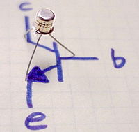
Transistor pins and schematic layout. (Wikipedia)
|
|
|
Goal :
|

|
|
Wired up.
|
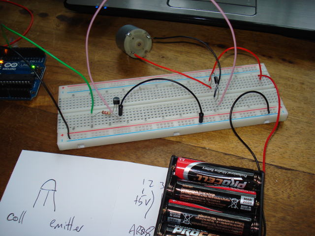
|
int T1 = 10;

void setup()
{

  Serial.begin(9600);

  pinMode(T1, OUTPUT);
}

void loop()
{
digitalWrite(T1, HIGH);
delay(15000);
digitalWrite(T1, LOW);
delay(15000);
}
|
With a resistor of 1K2 (1200) between base and arduino, and a voltmeter across the base and emitter:
part 1 - setting it LOW  = 0.45v - motor is ON
part 2 - setting it HIGH = 5.21v - motor is OFF
With a resistor of 100K (100,000) between base and arduino, and a voltmeter across the base and emitter:
part 1 - setting it LOW  = 5.45v - motor is OFF
part 2 - setting it HIGH = 5.59v - motor is OFF
So clearly the value of the resistor is critical. But why: with a bigger resistor, isn't the voltage always LOW ?
Why is it always HIGH ?
V = I x R.
5 = n x 1200; gives us 4.17 milliAmps mA
5 = n x 100,000; gives us 0.05 milliAmps mA

But that is with the battery plugged in as well - without the battery, the values return to normal :
Even with a 100K resistor, the value switches between 0V and 5V
|
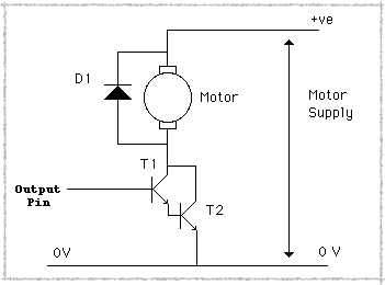
Darlington pair.
|
|
The darlington pair failed at first, since I had 2 different transistor types.
2907 and 2222
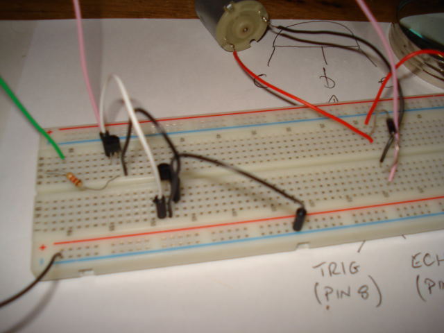
I put 2 x 2222 transistors as a pair and it worked well. The motor seemed to be spinning faster ?
|
Darlington pair wired up.
|
|
