
| A matrix LED |
|
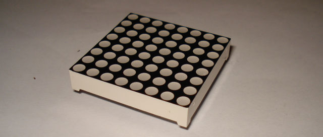
I had major problems getting this to work. All of the examples and tutorials I found did not work with my own matrix LED
(pictured above).
The problems centered around confusingly written code and poor (imo) comments within the code. Mainly, the arduino pin numbers
to control the rows/columns were just incorrect.
In the end, I wrote the code myself to work out which arduino pin controlled which row and column of the LED.
There's also a chip, the MAX7219, which I bought online earlier. It (should) control the LED via the i2c interface which (should)
reduce the wiring mayhem. I also intend to try shift registers, once I work out the arduino pins.
| Wired up according to the tutorial produced a mess of wiring, and a mess on the LED matrix. |

|
|
This is the wiring diagram that I finally used - try it, and the code below. |

|
This is the trial and error method that I used to work out which arduino pin controls which row or column. Get a pencil and paper handy - write down the arduino pin number, and then see whether a row or column flashes on the LED. If it does - write it down !
   /*
NOTE: Set the ROWS HIGH and the COLUMNS LOW. If this produces nothing, then set the ROWS LOW and the COLUMNS HIGH.
 Pin numbers:
 Matrix:
 * Digital pins 2 through 13,
 * analog pins 2 through 5 used as digital 16 through 19
Resistors - none used.
 */

// 2-dimensional array of row pin numbers:
const int row[8] = {
// ORIG  2,7,19,5,13,18,12,16 }; // This was in the original code tutorial I used. It gave me most of the rows and some of
   // the  columns lit up. Try and start with some LEDs lit; this makes it easiest for this code to work out what's right and wrong.
// tried : 12,16,2,7,19,5,13,18 }; // This was my second attempt
19, 18, 11, 4, 12, 6, 7, 16 };  // This was my correct sequence, swapped from the columns array

// 2-dimensional array of column pin numbers:
const int col[8] = {
// ORIG  6,11,10,3,17,4,8,9  };
//  tried : 11,4,6,3,17,8,9,18  };
  13, 17, 2, 10, 9, 3, 8, 5 };


void setup() {
  Serial.begin(9600);
  // initialize the I/O pins as outputs
  // iterate over the pins:
  for (int thisPin = 0; thisPin < 8; thisPin++) {
    // initialize the output pins:
    pinMode(col[thisPin], OUTPUT);
    pinMode(row[thisPin], OUTPUT);

  }

  // draw the screen:
  refreshScreenReWritten();
}

void flash(int arduinoPin)
{

 Serial.println("Writing to pin");
 Serial.println(arduinoPin);

for (int i = 0; i < 7; i++)
  {
  digitalWrite(arduinoPin, LOW);
  delay(500);
  digitalWrite(arduinoPin, HIGH);
  delay(500);
  }
}

void loop() {

 delay(2000);
 // Flash each arduino pin for 20 seconds
 // change the delays to fit your speedy mood
 for (int i = 2; i <= 19; i++)
   {
     flash(i);
     delay(1000);
   }

}

// Start by lighting every LED (or at least as many as possible, depending on whether your ROWS and COLUMNS are correct)
void refreshScreenReWritten()
{
  // set the ROWs to LOW
  for (int thisRow = 0; thisRow < 8; thisRow++)
  {
    digitalWrite(row[thisRow], LOW);
  }

  // set the COLUMNS to HIGH
  for (int thisCol = 0; thisCol < 8; thisCol++)
  {
    digitalWrite(col[thisCol], HIGH);
  }
}
|
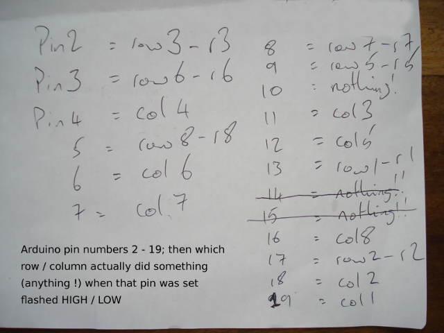
Running that sketch, and pencil / paper in hand, I jotted down which matrix row or column actually responded
when each arduino pin was set HIGH / LOW.
I also quickly realised that this is an ideal job for a couple of shift registers,
so once I have my pins and wiring worked out, that will be the next step.
|
These are the jotted notes that I was able to write. It gave me the info needed to correctly
create the row array and the column array with the correct, or likely, Arduino pin numbers. Compare the example array with my final array, and you will see just how far out the tutorials are. And yes, the tutorials were for the same piece of kit and the wiring was correct. |
|
Once I had the pin numbers correct, this quick sketch (below) correctly flashed rows 1 - 7, and then columns 1 - 7.
Now, the next step will be to develop code that prints something useful.
NOTE ! : There are 2 routines; one to flash the rows and one to flash the columns. The state of the row/column
has to be correct (either high or low) once you have finished with it. Try it reversed to see what I mean. Eventually,
all the LEDs go out.
/*
 Pin numbers:
 Matrix:
 * Digital pins 2 through 13,
 * analog pins 2 through 5 used as digital 16 through 19
 */


// 2-dimensional array of row pin numbers: These are correct for my wiring
const int row[8] = {
19, 18, 11, 4, 12, 6, 7, 16 };

// 2-dimensional array of column pin numbers: These are correct for my wiring
const int col[8] = {
  13, 17, 2, 10, 9, 3, 8, 5 };

void setup() {
  Serial.begin(9600);
  // initialize the I/O pins as outputs
  // iterate over the pins:
  for (int thisPin = 0; thisPin < 8; thisPin++) {
    // initialize the output pins:
    pinMode(col[thisPin], OUTPUT);
    pinMode(row[thisPin], OUTPUT);
  }

  // draw the screen:
  refreshScreen();
}

void flashRow(int arduinoPin)
{

 Serial.println("Writing to pin");
 Serial.println(arduinoPin);

for (int i = 0; i < 2; i++)
  {
  digitalWrite(arduinoPin, HIGH);
  delay(200);
  digitalWrite(arduinoPin, LOW);
  delay(200);
  }
}
void flashCol(int arduinoPin)
{

 Serial.println("Writing to pin");
 Serial.println(arduinoPin);

for (int i = 0; i < 2; i++)
  {
  digitalWrite(arduinoPin, LOW);
  delay(200);
  digitalWrite(arduinoPin, HIGH);
  delay(200);
  }
}

void loop() {

 delay(2000);

 for (int i = 0; i <= 7; i++)
   {
     flashRow(row[i]);
     delay(300);
   }
 for (int i = 0; i <= 7; i++)
   {
     flashCol(col[i]);
     delay(300);
   }

}

void refreshScreen()
{
 // set the ROWs to LOW
  for (int thisRow = 0; thisRow < 8; thisRow++)
  {
    digitalWrite(row[thisRow], LOW);
  }

  // set the COLUMNS to HIGH
  for (int thisCol = 0; thisCol < 8; thisCol++)
  {
    digitalWrite(col[thisCol], HIGH);
  }
}
|
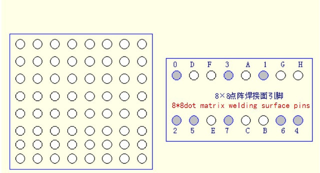
Incidentally, I also found the following information:
PIN 1: rotate the matrix so that the text on the side is facing towards you; Pin 1 is now bottom left.
Remember that pin 9 will now be top right and pin 16 is top left.
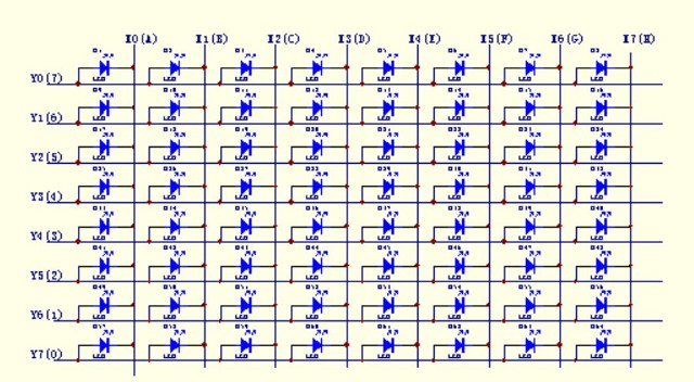
I also worked with these wiring diagrams.
|
|
Good luck and have fun. Chuck a resistor in if you use an external 5V supply !